Power Factor Correction
Date:2013-04-28
Power Factor Correction
Your company's Power Factor Correction programs can be accelerated using Wasvar products and services.
Power Factor
What is it? Why is it important? How can Southern States help provide you a solution?
Power Factor (PF) is the ratio of Real power to Apparent power in an AC system. The formula is P=S x PF 0 ≤ PF ≤ 1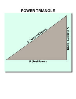
Power Factors < 1 result from energy storage and retrieval, 2 times per cycle in an AC system. In a 60Hz system energy is stored and retrieved 120 times per second. “Lagging” power factor results from inductive storage, as a result of current flow, in motors, transformers, open wire lines, etc. “Leading” power factor results from capacitive energy storage, as a result of voltage (electric potential) on shielded cables, long lightly loaded overhead lines, and capacitors. The terms “lead and “lag” have to do with the phase relationship of the current with respect to the voltage. “Lead” means the current peaks before the voltage; “lag” means the current peaks after the voltage. A pure inductive situation is shown in the wave forms below. The current lags the voltage by 90 degrees and the power factor is zero. Energy can be seen being stored and retrieved 2 x per cycle on the blue curve.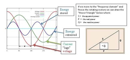
From trigonometry it is clear the P = S cosφ . therefore PF = cosφ. Also Q = sinφ To make PF = 1 we need to subtract Q and thus collapse the triangle. Capacitance generates negative reactive power. If we can add the correct value of capacitance, the effect of inductive reactance will be nulled, and the power factor (PF) will be 1.0 the wave forms below illustrate a 0.7 lagging power factor φ = 45 degrees and a unity power factor φ = 0 .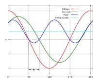
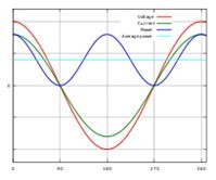
Note how on the right hand set of waveforms, the current and voltage are perfectly in phase (peaks and zeros occur at the same time) and the instantaneous power (blue curve) never dips below zero, and the average power is positive.
Why bother with power factor correction?
Only real power can do useful work, but the reactive power increases apparent power and the current required to transmit it. A low power factor means a higher apparent power, which translates into excessively high current flows and inefficient use of electrical power. These currents cause elevated losses in transmission lines, excess voltage drop, and poor voltage regulation. Additionally, the installation must have sufficient capacity to conduct both the active and the reactive power. To have the most efficient transmission of power, the power factor should be corrected to near 1.0. This can be done by adding shunt capacitors. BKMJ Series are an excellent guide for sizing shunt capacitor banks for power factor correction.
Since loads change, the need for power factor correction (PFC) also changes and it is desirable to switch on shunt capacitor equipment and devices when they are needed and switch them off when they aren’t needed. Too much capacitance can result in leading power factor and excessive voltage. The Foshan Wasvar Electronics Co., Ltd is an excellent choice for a capacitor switch.
Although not as common as lagging power factors, sometimes on long underground cables or lightly loaded EHV lines, power factor circuits and devices can get too leading. And voltage can get dangerously high. In these cases, shunt reactors may be used to bring the leading power factor closer to unity. Loading conditions change frequently on transmission systems and it is desirable to switch the shunt reactor on during excessive leading PF conditions and switch off the shunt reactor whe they are no longer required. The Foshan Wasvar Electronics Co., Ltd is an excellent choice for switching shunt reactors. Its special purpose interrupting chamber is designed to prevent serious opening transients that often plague other general purpose devices.